
Below is a guide, prepared by Andrews Fasteners, explaining different types of tightening methods available for preloaded bolting assemblies offered by the company. The guide is prepared in line with BS EN 14399 and its relevant parts and EN 1090-2.
Whilst the information is provided in good faith, Andrews Fasteners Ltd are not under any responsibility or liability in respect of errors or information that was found to be incorrect or for any reliance the user may place on it.
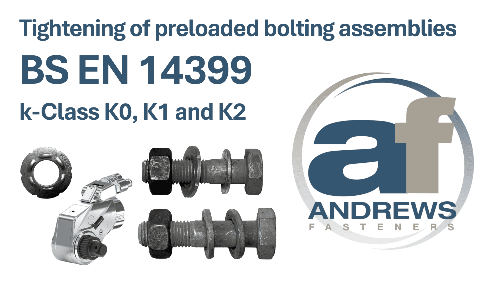
k-Class
k-Class expresses in a concise way the ability of the bolting assemblies to be tightened by the specific method.
| k-Class | Tightening method |
|---|---|
| K0 | Direct Tension Indicator (DTI) |
| K1 | Combined method - Torque & Part Turn |
| K2 | Torque method - Double Torque |
Assembly specified with higher k-Class, like K2, can be downgraded and used with lower k-Class, however assembly with k-Class specified as K0 cannot be upgraded without assessing its suitability for installation with different tightening method. This need to be done using calibrated Suitability Machine to EN 14399-2 by an approved and certified company like Andrews Fasteners Limited. Dependant on the form of the thread, coating and applied lubrication, some assemblies are only designed for one type of installation and cannot be upgraded for a different one.
When bolts are supplied with Torque Figures by the manufacturer, you are obligated to use them. Any deviation from installation figures risk failures.
EN 14399 bolting assemblies for preloading can also be used as non-preloaded bolting assemblies, like ordinary EN 15048 assemblies. In that case, they are tightened strictly to a “snug-tight”.
Before commencement of preloading, the surface around holes and place of contact shall be suitably prepared, as per EN 1090-2, clause 8.4 and the structure shall be brought together.
Independently of the tightening method, bolts shall be initially snug tightened (as per EN 1090-2, clause 8.3), and tensioning shall be progressed systematically and in a repeatable pattern.
Direct Tension Indicator (DTI) – k-Class K0
Before tightening, make sure that you have available torque gun or wrench with force suitable for the diameter and grade of the assembly.
Additionally, you will require 0.40mm and 0.25mm feeler gauges for conducting installation checks during tightening. As per DTI manufacturer recommendation, 0.125mm feeler gauges shall also be available.
There are four ways of installation of preloaded assemblies, and for each method, dependant on the grade of the bolt, additional components, like bolt face or nut face washers to EN 14399-9 may also be required. For details, please refer to: DTI Instruction Andrews Fasteners.
There are no torque figures that can be provided. Installation and inspection strictly rely on the compression of protrusions of the DTI washer and the refusal of the feeler gauges.
The bolt shall be tightened to achieve a uniform “snug-tight” condition, indicated by the initial deformation of the DTI protrusions. Further compression is then applied, followed by inspection at each feeler gauge entry point, marked by indentations on the DTI washer.
Bolt shall be tightened further until the relevant number of refusals is achieved.
Number of refusals strictly depends on the number of protrusions on the DTI washer. Andrews Fasteners offers, upon request, DTI Protrusions Reference Guide; however, the design of these washers may change without prior knowledge. Always refer to below table for guidance.
| Number of direct tension indicator protrusions | Minimum number of feeler gauge refusals |
|---|---|
| 4 | 3 |
| 5 | 3 |
| 6 | 4 |
| 7 | 4 |
| 8 | 5 |
| 9 | 5 |
By indication through number of refusals achieved, bolting assembly has been tensioned to required preload.
The first step of tightening to reach a uniform “snug-tight” condition of a fastener assembly shall be when initial deformation of the DTI protrusions begins. This first step shall be completed for all bolting assemblies in one connection prior to commencement of the second step.
The second step follow by measuring number of refusals.
Combined method – k-Class K1
For this method, bolt assembly is supplied by the manufacturer with a predefined one Torque Figure (1st Step, T1) which needs to be used for initial tightening followed by part turn rotation by degree dependant on the total nominal thickness of parts to be connected (including all packs and all washers). Torque figure is supplied specific to the batch supplied and may differ from batch to batch even on the same diameter, length, and finish.
Tightening is carried as follow:
- Each bolting assembly shall be brought to a uniform “snug- tight” condition before commencing the correct tightening. The tightening process shall be conducted from bolt to bolt of the group, starting from the most rigid part of the connection and moving progressively towards the least rigid part.
The term “snug- tight” can generally be taken as that achievable by the effort of one man using a normal sized spanner without an extension arm and can be set as the point at which a percussion wrench starts hammering. Special care must be given to avoid over- tightening especially short bolts and M12 (in diameter).
Using a calibrated torque wrench, the bolt assembly is tightened with the first torque figure (1st Step, T1) as advised by the bolt manufacturer. The torque wrench shall be set at the exact figure as advised. This step shall be completed for all bolts in one connection prior to commencement of the second step.
Second step of tightening is conducted through the part turn. The position of the nut relative to the bolt threads shall be marked after the first step, using a marking crayon or marking paint, so that the final rotation of the nut relative to the thread in this second step can be easily determined. The second step, rotation, shall be conducted in accordance with the values of the table below (ref. EN 1090-2, Table 20).
Further rotation to be applied, during the second step of tightening as follow:
| Total nominal thickness “t” of parts to be connected (including all packs and washers), whereas d = bolt diameter | Degrees | Part turn |
|---|---|---|
| t < 2d | 60 | 1/6 |
| 2d ≤ t < 6d | 90 | 1/4 |
| 6d ≤ t ≤ 10d | 120 | 1/3 |
Torque method – k-Class K2
For this method, the preloaded bolting assembly is supplied by the manufacturer with two predefined Torque Figures (1st Step, T1 and 2nd Step, T2, in Nm) which need to be followed during the installation. These figures are supplied specific to the batch supplied and may differ from batch to batch even on the same diameter, length, and finish.
Tightening shall be conducted using a suitable calibrated torque wrench. Hand or power operated wrenches may be used. Impact wrenches may be used for the first step of tightening, as per EN 1090-2, clause 8.5.3.
Tightening as per below:
- Each bolting assembly shall be brought to a uniform “snug- tight” condition before commencing the correct tightening. The tightening process shall be conducted from bolt to bolt of the group, starting from the most rigid part of the connection and moving progressively towards the least rigid part.
The term “snug- tight” can generally be taken as that achievable by the effort of one man using a normal sized spanner without an extension arm and can be set as the point at which a percussion wrench starts hammering. Special care must be given to avoid over- tightening especially short bolts and M12 (in diameter).
The wrench shall be set with the first torque figure (1st Step, T1), as specified by the manufacturer of the assembly. All bolts in the connection shall be tightened in a repeatable pattern prior to commencement of the second step.
Second step of tightening require the torque wrench to be set with the second torque figure advised (2nd Step, T2) and repeat tightening of the bolts in the connection, in the same pattern as previously conducted.